This guide covers the proper alignment and calibration procedures for the TS-3 Master Wheel Truing Stand.
Before You Begin
Gather the following tools:
- FFG-2 Frame and Fork Dropout Alignment Gauge Set
- 1554-1 Centering Gauge
The TS-3 operates with the wheel skewer in a closed and tightly locked position. This ensures the wheel sits in a repeatable, stable location. When a skewer is left open versus locked, the wheel may shift slightly. What matters most is that the wheel consistently ends up in the same spot once the skewer is secured. Always verify TS-3 calibration against this locked position, using the 1554-1 centering gauge together with a quick-release skewer.
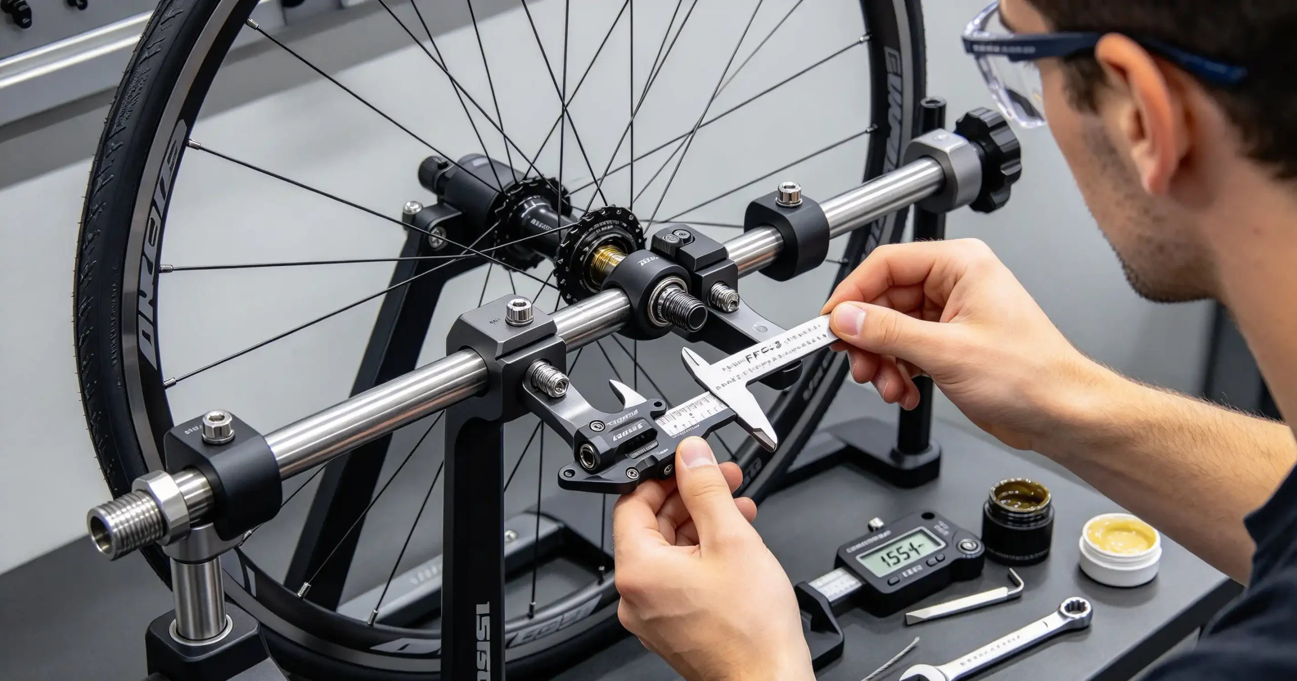
Two uprights (#1510-2) travel along two minor shafts (#1525-2) and one major shaft (#1524-1). These shafts need to remain parallel and concentric. How well these shafts are aligned directly affects the alignment of the two V-plates (#1523-2). To check this, insert the FFG-2 Frame and Fork Alignment Gauge Set into the V-plates. Set up the FFG-2 as you would on a front fork, with the spacer positioned to the outside of the plates.
Draw the two V-plates together by using the center link handle (#1527-1). Never bend the V-plates to fix alignment issues. Alignment exists in two planes: front-to-back and vertical (up-and-down). Front-to-back misalignment is corrected by realigning the three shafts. Vertical misalignment is addressed using shims placed behind the V-plates. Figure 1 illustrates a front-to-back alignment issue.
Correcting V-Plate Front-to-Back Alignment
Begin by loosening the end cap bolts (#1516-2) on both sides. Using the FFG-2, push the arms back into front-to-back alignment, as shown in Figure 2. While holding the FFG-2 with one hand, snug the end cap bolts. Tighten the middle bolt of one cap first, then the middle bolt of the opposite cap. Return to the first side and snug a side bolt, then move diagonally to the other side and snug that cap bolt. Continue this alternating pattern until all bolts are fully tight. Recheck the FFG-2 to confirm improved alignment.
Having the TS-3 bolted down makes servicing easier. A practical approach is to pre-drill your workbench using the four-hole pattern on the base.
Correcting V-Plate Vertical Alignment
First, identify which V-plate needs adjustment. In Figure 3, the right-side V-plate should rotate so the FFG-2 moves upward.
Loosen the bolts securing the V-plate, then gently wiggle the V-plate away from the upright. Insert a very thin shim behind the V-plate. If the V-plate needs to rotate upward, place the shim at the bottom backside of the V-plate, between the V-plate and upright. If it needs to rotate downward, place shim stock behind the V-plate above the top bolt, between the V-plate and upright. A single strand of bicycle brake or derailleur cable typically works well as shim material. Make sure the wire end does not protrude or become visible. Figure 4 shows the V-plate after loosening, while Figure 5 shows it after shim placement. Note the slight gap at the bottom of the V-plate in Figure 5.
Caliper Arm Alignment
Occasionally, the caliper arm (#1513-1) may fall out of alignment. After verifying or adjusting V-plate alignment, check the caliper arm. Install the 1554-1 centering gauge and pull it outward toward you, as shown in Figure 6. Secure the centering gauge with the skewer. Rotate the caliper bracket (#1514-1) fully backward, away from the stand, as seen in Figure 7. This reveals the “knuckle” or upper portion of the caliper arm. Raise the caliper arm toward the gauge. The center of the caliper arm should line up closely with the center of the centering gauge. If it is noticeably off, the caliper arm can be adjusted.
CAUTION: Bending components to achieve alignment always carries risk, just as with a bicycle. The caliper arm or caliper bracket could fail. Send the unit back to Park Tool for repair, or simply replace the arm. There is an alternative method that avoids bending the caliper arm. You can file the steel stud beneath the calipers (#1515-1L and #1515-1R). This stud rests against the caliper actuator stud (#1533-1). The caliper sitting farther from the centering gauge can be brought inward by shortening the stud. Use a small jewelry file and remove only a tiny amount of material at a time. See Figure 8.
Caliper Shaft Adjustment
The caliper shaft (#1528-1) opens and closes the calipers (#1515-1L and #1515-1R). If play develops in the shaft, the calipers may shift, leading to inconsistent centering. Grip the end knob and wiggle the handle side to side. Watch for any caliper movement. Adjust play using the setscrew 1569-2 on the right side of the caliper bracket (#1514-1). See Figure 9. Additionally, apply grease to the top of the caliper actuator stud (#1533-1) for smoother operation.
Center Link Handle (#1527-1)
The center link handle (#1527-1) may loosen over time. If the handle becomes loose within the center link (#1521-1), the stress of opening and closing transfers to the handle’s threads rather than the flange behind the threads. This can lead to handle failure. Ensure the handle is fully tightened into the center link. Apply a thread-locking compound if needed. If the handle will not tighten completely, add a washer to the thread. A slight gap, as shown in Figure 10, indicates the handle is not secure.